This guide is the result of several years of work by a small group of arcade enthusiasts to unravel the secrets of the security implementation found in one of the most loved and popular arcade game platforms. Thanks to this work it is now possible to fully preserve most Sega 16 bit systems enabled with security as fully working unmodified originals.
Unlike previous projects this time we recommend the usage of a dedicated pcb to interface with the chips due to the high pin count involved in the programming.
Additional details of the inner workings of Sega's FD security modules will be published over time in this blog. Work on the earlier MC 8 bit modules used in some System 1 / 2 boards and sound of Sega 16 is still in progress and will be published when completed.
Thanks to everyone who has helped make this a reality including all kind donors and testers.
Sega Hitachi FD1089 / FD1094 Security Programming Guide
This document will guide you through the basics of preparing your setup and testing the a clean desuicide method on any known Sega 16 / 18 / 24 / X board revisions using Hitachi FD1089 or FD1094 modules. You can find a pdf copy of this guide and code on the following link: https://github.com/ArcadeHacker/ArcadeHacker_Sega_Hitachi
What's needed
Arduino programmer hardware
- 1x Arduino Mega 2560 rev 3 (with USB cable)
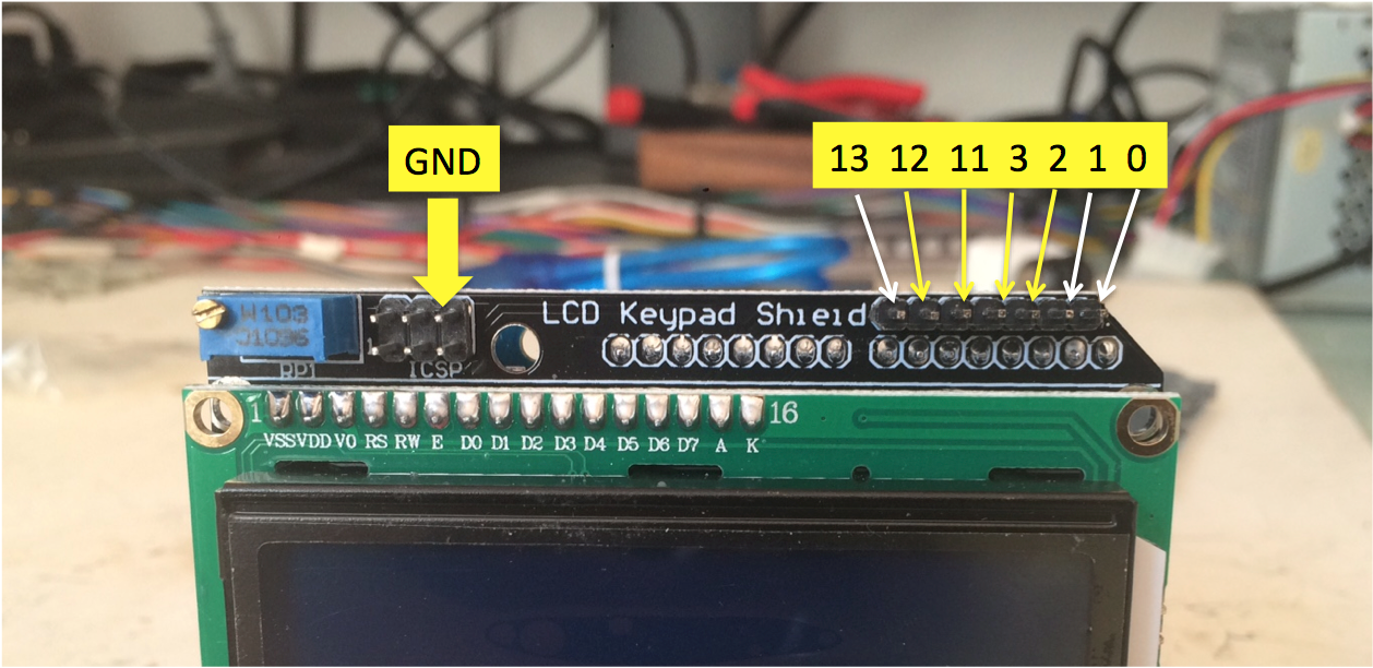
- 3x 40 Pin Male Single Row Pin Header 2.54mm spacing
- 1x 64 pin IC socket 2.54mm spacing, a couple of options:
- 1x ArcadeHacker FD1089 / FD1094 arduino mega shield pcb
- Build / order your own:
- Pcbway.com 72h on demand fabrication for $5
- https://www.pcbway.com/project/shareproject/W38238MSJ9_W38238MSN8_SegaFD_2560v2.html
- Design / customize your own:
- Soldering iron and solder
Sofrware
- Computer with Arduino IDE Software
- ArcadeHacker Sega Hitachi FD1089 or FD1094 Arduino programs
Assembling and preparing your Arduino programmer
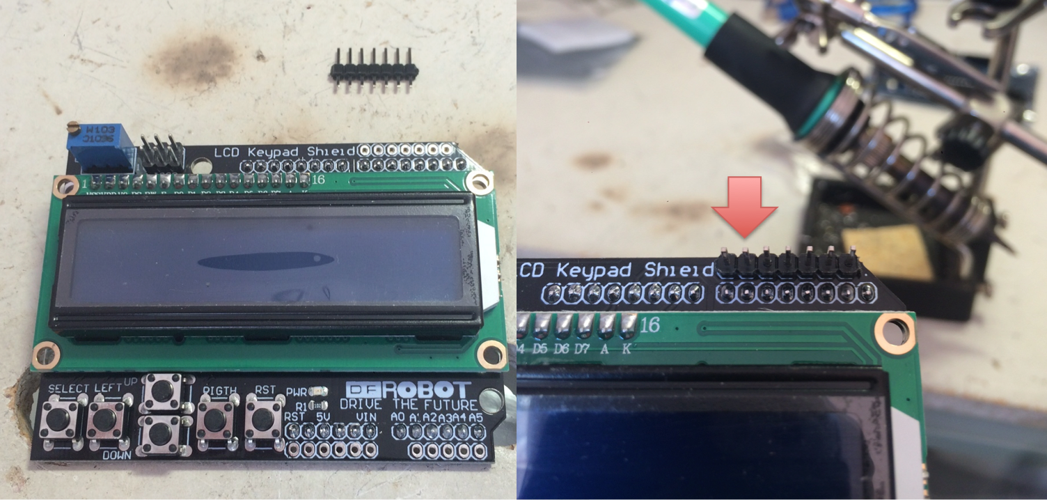
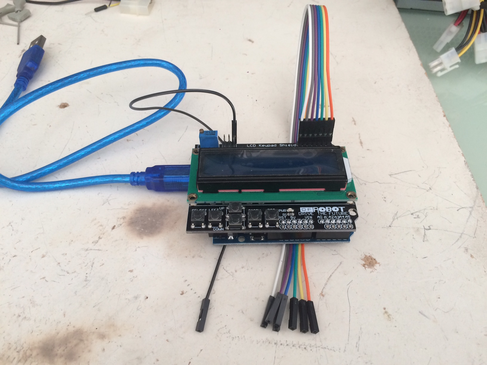
This step is pretty straight forward, solder all the pin headers to your programmer pcb as well as the IC 64pin socket. The fully assembled pcb looks like this:

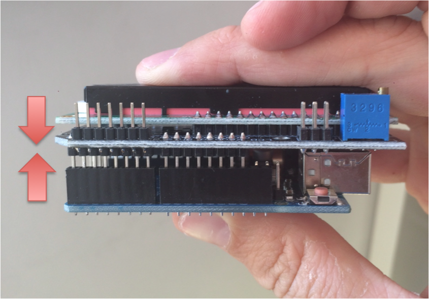
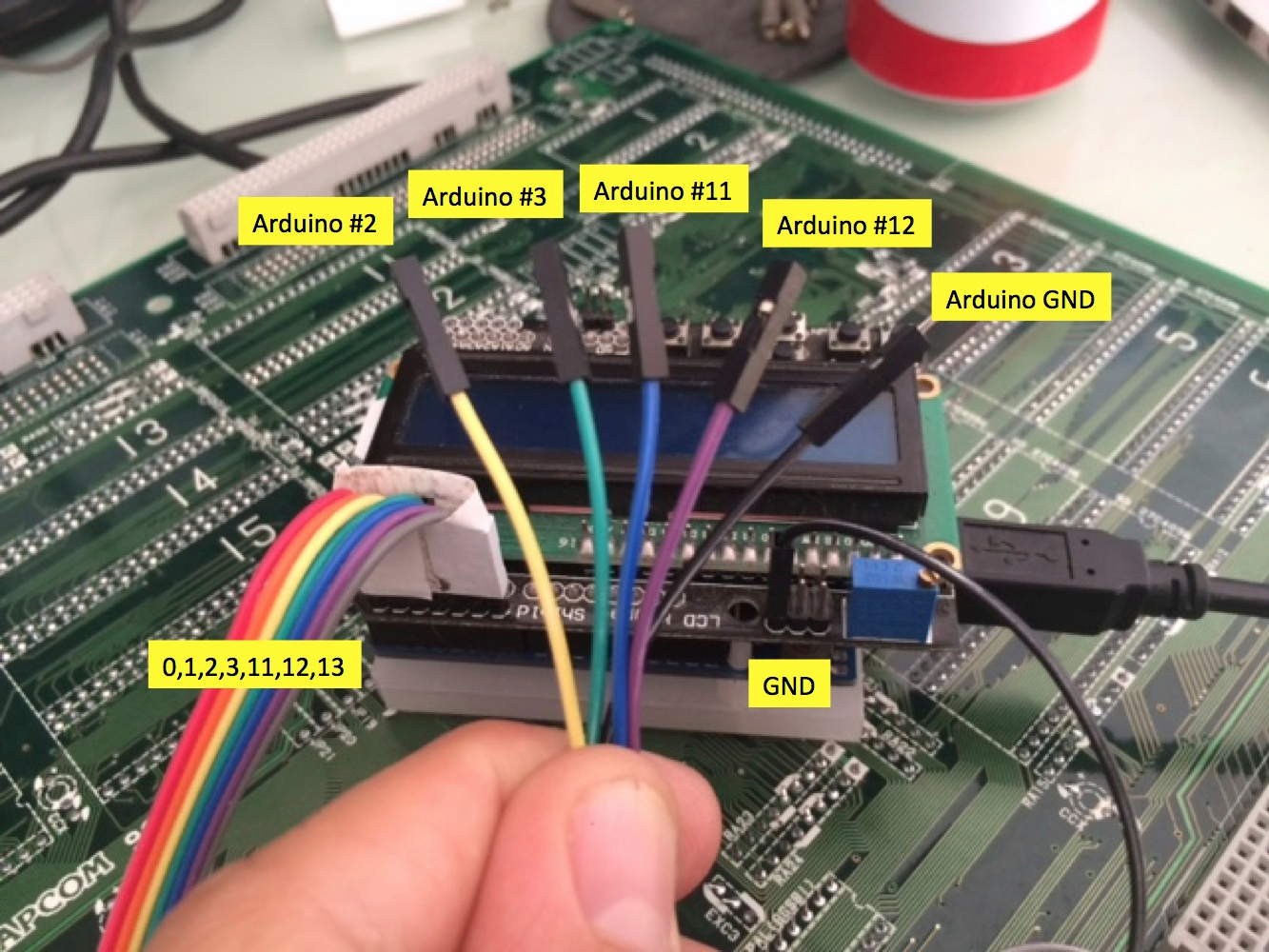
After the pcb shield is ready just sandwich it together with your Arduino Mega 2650.

Download and install software for your OS from https://www.arduino.cc/en/Main/Software
Select the right arduino board type before connecting your arduino to your computer. Tools -> Board -> Mega 2560.

Connect the Arduino to your computer by plugin the USB cable and choose the correct serial port in Tools -> Port.
Open the ArcadeHacker Sega FD1094 or FD1089 .ino file in the Arduino environment. Compile and Upload the sketch to the Arduino unit.
Open the Arduino IDE serial monitor found in Tools -> Serial Monitor. Configure the two settings found in the lower right part of the serial monitor window as follows: Carriage Return and 115200 bauds.

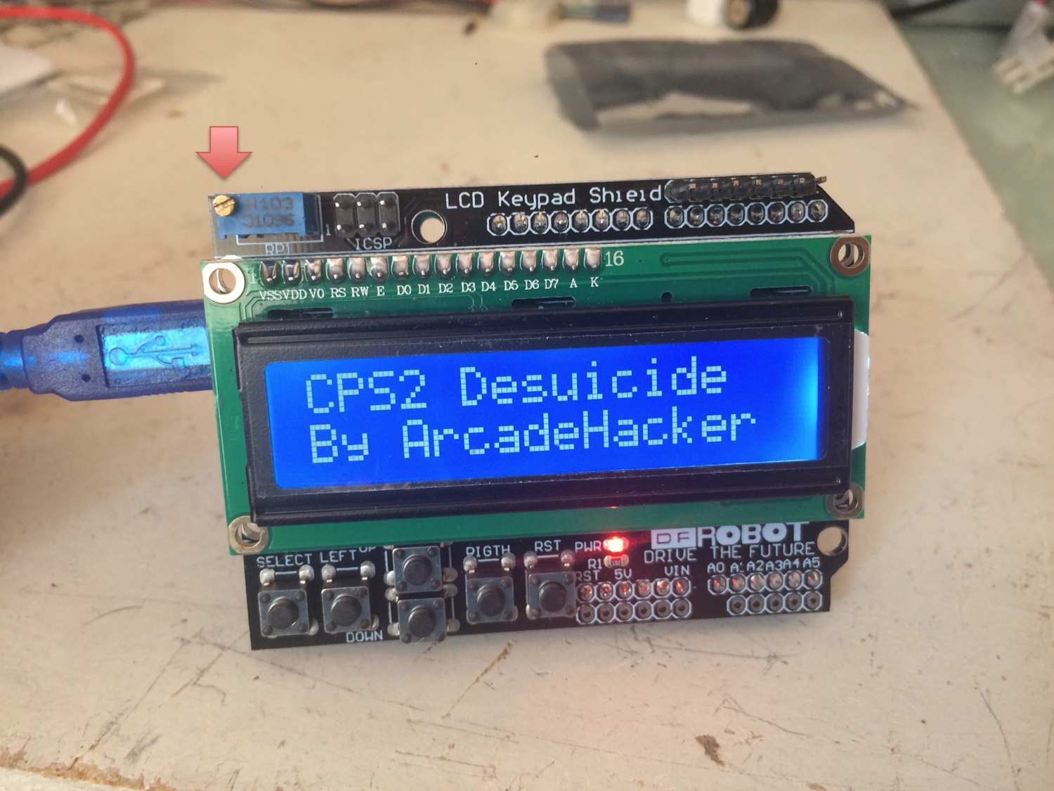
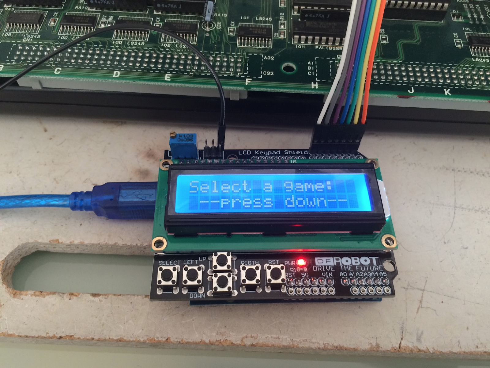
Close and open the serial monitor, you should now see the following text on screen. If this is the case you have successfully setup and configured your Arduino programmer.

Programming security keys
Look inside the Arduino FD1089 or FD1094 code for the game you intend to program the encryption keys into the FD chip and uncomment the desired line of code. Only one game can be uncommented at any time, don't forget to comment the default blank game setting at the beginning of the list.

If the above was done correctly you should now compile and upload the program to your Arduino without problems. Once the upload process is finished open the serial monitor found in Tools. The program prompt should display the game you have configured.

For this example we have selected "eswat" a System 16 game using the Hitachi FD1094 security module "317-0160". FD1094 security modules can be repurposed for any game and it is not required that a label in the cpu module matches the intended game security key to be programmed. This will not be the case with FD1089 modules as two different encryption schemes exist (FD1089A & FD1089B): A variants of the chip are only compatible with games roms for other A variants, and B variants for B games only.

Having inserted the module in the socket we can proceed to program the security keys by typing w and pressing enter. Make sure you replace the module battery if necessary before attempting a key load, a new battery will last at least 20-30 years so don't expect to have to repeat this often. Once the process finishes you can disconnect the Arduino module from your computer and remove the cpu module.

If you would like to verify that the contents of the cpu match the intended configuration loaded in your programmer you can perform a verification by typing v and pressing enter. This verification compares a 1 bit parity per byte calculated internally by the security module against the encryption configuration in your Arduino.
WARNING: This verification procedure is 100% safe in FD1094 modules. Unfortunately this is not the case with FD1089 modules as the verification will delete the data inside your module, please do not attempt verification with any valuable FD1089 modules especially if currently undumped or not preserved in Mame.
Final words
This is all there is to preserving your Sega FD1089 / FD1094 modules as working units, we hope this milestone will help you and the rest of the arcade community preserve your loved games as originals and stop the general discarding of Sega Hitachi modules.
As mentioned in the opening of this post, a number of follow up articles in this blog will reveal the inner workings and curiosities of these artfully crafted security modules.
Happy preservation.